Home
/ Sfd Bmd Formula : Beam Analysis Excel Spreadsheet Civilengineeringbible Com _ Bending moment diagram (bmd) shear force diagram (sfd) axial force diagram.
Sfd Bmd Formula : Beam Analysis Excel Spreadsheet Civilengineeringbible Com _ Bending moment diagram (bmd) shear force diagram (sfd) axial force diagram.
Sfd Bmd Formula : Beam Analysis Excel Spreadsheet Civilengineeringbible Com _ Bending moment diagram (bmd) shear force diagram (sfd) axial force diagram.. Draw the sfd and the bmd, noting all local maximum and minima values. Bending moment at a section x from end a is given by m x = + w, x ……… (straight line) at x=0, ma=d ; Bending moment formula for simply supported beam with uvl. Example on simply supported beam 7. Forces and stresses in beams.
Axial force diagrams come additionally for column design. Diagrammatic convention for supports roller supports hinge support fixed support link support fig. Support conditions axial force, shear force and bending moment three forces are required to maintain internal equilibrium at every section of a beam. Sfd & bmd for continuous beam. Bmd = bending moment diagram e = modulus of elasticity, psi or mpa i = second moment of area, in 4 or m 4 l = span length under consideration, in or m
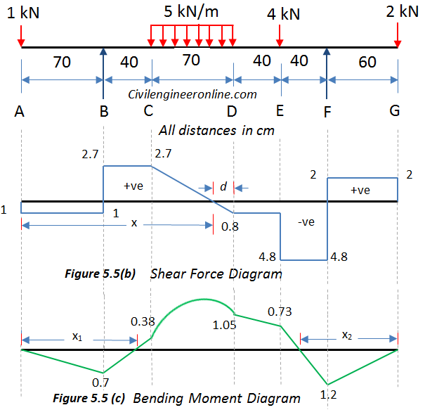
Solving For Sfd And Bmd Of Overhanging Beam Prob 5 5 Civil Engineer Online from civilengineeronline.com Shear force diagram (sfd) & bending moment diagram (bmd) form the basis for design of beams in general. Sfd = shear force diagram. How to find bending moment of uniformly varying load quora. Will thus be a triangle having zero ordinate at a and wl at b. Draw the shear force v and bending moment m diagrams for beams shown below study. Also with the implementation of conjugate beam method or moment area method, this beam. Shear force diagram (sfd) & bending moment diagram (bmd) form the basis for design of beams in general. In this course we will be discussing architectural plans of industrial building, structural drawing of industrial building, soil investigation proposal, soil investigation report, dead load and live load calculation acting on our slabs, beams.
Calculate the reactions at the supports of a beam.
Numerical on sfd and bmd on simply supported beams problems on simply supported beams. If the length of this. Sfd and bmd examples.use equilibrium conditions at all sections to. Sfd & bmd, shear force diagram and bending moment diagram, sfd, bmd notes. Find the internal torques at points b and c of the circular shaft subjected to three concentrated torques solution: According to unit load method the deflection of a joint of truss is given by the following formula. Sfd bmd formula / why i find the shear force digram and bending moment diagram of a beam or colume and what is the uses of sfd and bmd in the field quora / v = v0 + (negative of area under the loading curve from x0 to x). What is the shape of bmd for this diagram? Chapter 3 shearing force and bending moment diagram fet construct shear force and bending moment diagram for the beams shown label all significant points on each identify maximum moments both positive negative along with respec study mechanics of materials chapter. 3 kn/m 4 m a b example 8. Bending moment formula for simply supported beam with uvl. Jahangirabad instiute of technology barabanki department of mechanical engineering elements of mechanical engineering ravi vishwakarma 31/12/16 ravi vishwakarma 1 2. Use coupon foundation to buy the course at 9.99$.
A simply supported beam cannot have any translational displacements at its support points, but no restriction is placed on. 3 kn/m 4 m a b example 8. Sfd and bmd examples.use equilibrium conditions at all sections to. Forces and stresses in beams. Since, sfd is always parallel to the x axis (as load is always discreet) bmd will always be a straight line.
Continuous Beam Four Span With Udl from structx.com Use this beam span calculator to determine the reactions at the supports, draw the shear and moment. Forces and stresses in beams. If the length of this. Bending moment formula for simply supported beam with uvl. Numerical on sfd and bmd on simply supported beams problems on simply supported beams. According to bis, the standard symbols used for sketching sfd are point load. In this course we will be discussing architectural plans of industrial building, structural drawing of industrial building, soil investigation proposal, soil investigation report, dead load and live load calculation acting on our slabs, beams. Get the unknown sf and bm.
Sfd (kn) bmd (knm) calculate the shear force and bending moment for the beam subjected to the loads as shown in the figure, then draw the shear force diagram (sfd) and bending moment diagram (bmd).
Calculate the reactions at the supports of a beam. Sfd & bmd, shear force diagram and bending moment diagram, sfd, bmd notes. Learn vocabulary, terms and more with flashcards, games and other study tools. Numerical on sfd and bmd on simply supported beams problems on simply supported beams. Lesson 7 of 21 • 26 upvotes • 11:52 mins. Sfd (kn) bmd (knm) calculate the shear force and bending moment for the beam subjected to the loads as shown in the figure, then draw the shear force diagram (sfd) and bending moment diagram (bmd). Shear force diagram (sfd) & bending moment diagram (bmd) form the basis for design of beams in general. The external and internal diameters of the hollow cast iron column are 5cm and 4cm respectively. Diagrammatic convention for supports roller supports hinge support fixed support link support fig. Also with the implementation of conjugate beam method or moment area method, this beam. Sfd = shear force diagram. Sfd & bmd for continuous beam. The beam is supported at each end, and the load is distributed along its length.
Sfd & bmd for continuous beam. Bending moment at a section x from end a is given by m x = + w, x ……… (straight line) at x=0, ma=d ; Strength of material or mechanics of solid text of bmd and sfd. The external and internal diameters of the hollow cast iron column are 5cm and 4cm respectively. Setting the bending diagrams of beam.
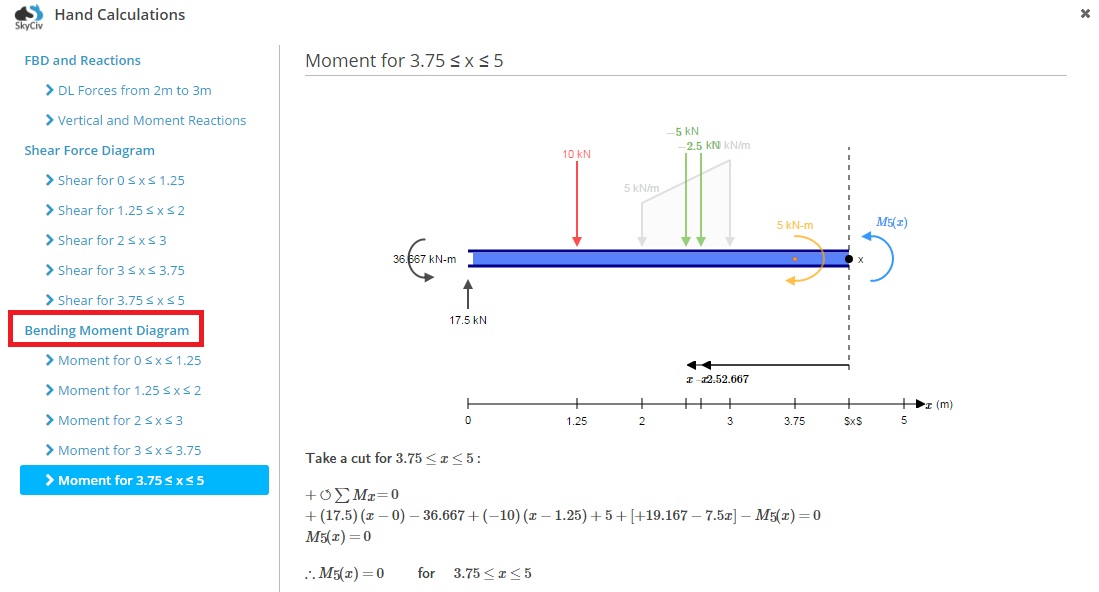
How To Calculate Bending Moment Diagrams Skyciv from skyciv.com Sfd = shear force diagram. Numerical on sfd and bmd on simply supported beams problems on simply supported beams. Axial force diagrams come additionally for column design. The beam is supported at each end, and the load is distributed along its length. Below are the beam formulas and their respective sfd's and bmd's; Draw sfd and bmd using the formula. Sfd bmd of uvl simply supported beam shear force diagram and bending moment unacademy. Setting the bending diagrams of beam.
Calculate the reactions at the supports of a beam.
Below are the beam formulas and their respective sfd's and bmd's; Sfd & bmd, shear force diagram and bending moment diagram, sfd, bmd notes. Diagrammatic convention for supports roller supports hinge support fixed support link support fig. Numerical problems on rankine's formula. • determine reactions at supports. Shear force diagram (sfd) & bending moment diagram (bmd) form the basis for design of beams in general. Forces and stresses in beams. Learn vocabulary, terms and more with flashcards, games and other study tools. In this course we will be discussing architectural plans of industrial building, structural drawing of industrial building, soil investigation proposal, soil investigation report, dead load and live load calculation acting on our slabs, beams. Hence, sfd and bmd reduce the probability of the structure's failure. Axial force diagrams come additionally for column design. .ends sfd and bmd at both ends 3/6 simply supported udl beam formulas written by haseeb monday, 12 july 2010 17:50 fig:11 fig:12 from theformulas sfd midspan and bmd for to calculating. Strength of material or mechanics of solid text of bmd and sfd.

 shear force diagram (sfd) axial force diagram.)